Kicker WX10000.1 Warhorse

MSRP $9,999.99
With dimensions measuring 35 inches by 17 3/4 inches by 3 3/4 inches and a total weight of 66 pounds, the Warhorse is a monster of an amp. On the other hand, it's about the same size as amps with much lower power output, say, around 3,000 watts. That raises the question of whether it's efficient enough to actually make its claimed 10 kilowatts of power.

Before I get into it, let's look at what we're working with. Kicker has rated this beast at 10,000 watts into a 2-ohm load, or 5,000 watts into a 4-ohm load. As far as the class, it's not D, AB, or anything else you might be familiar with. In fact, the operation of this amp is so unique that Kicker has applied for a patent so they can classify it. I'll do my best to explain all that, but in the meantime study up on Class D operation and pulse width modulation as a reference point.

The amp has the usual features you'd expect to find in a big subwoofer amp like 24dB/octave highpass and lowpass crossovers, 0 to 18dB of bass boost at 40Hz, and the absence of fuses. In addition, the Warhorse sports three ought-gauge power and three ought-gauge ground cable connectors, and two pairs of 8-gauge Anderson connectors for the speaker outputs. No, it's not a stereo amp-strictly mono.

Eight indicator lights on the control panel reveal several conditions. PWR illuminates when the amp is on and working properly. NET shows that you're connected to the optional WXRC remote control, which offers expanded crossover slope selections in addition to being able to make adjustments from the driver seat. There are also LED indicators for over-voltage, under-voltage, overheated and short-circuit. The X-BNDW light tells you that you have set the lowpass crossover lower than the highpass crossover, while the Service light lets you know that you probably need to get the amp back to the Kicker service department or at least call the tech support line.

The unit looks like an oversized black briefcase with extruded fins running the length of each side. The top is an engraved black aluminum plate with a molded plastic hood over the entry for the power cables. The cast endcaps house the cooling fans and provide a very structural look to the whole unit. The power and ground-all six ought-gauge cables-come into the amp at almost the center of the top plate. All other connections and controls are hidden halfway along the nearside heat sink under a matching cover plate.

Circuitry
Looking under the cover, the first thing you'll notice is the four planar transformers and the huge buss bars that run across the topside of the main circuit board. The transformers are about the size of your hand and resemble a stack of pancakes. The primary and secondary windings are stacked on top of each other rather than being several strands of wire intertwined. The turn ratio is 19 to 1, meaning there are literally 19 turns of flat wound copper for each secondary and one turn for each primary. The primary looks more like a big horseshoe-shaped PCB trace. Each planar transformer is rated at 5,000 watts for a total capacity of 20,000 watts.

The positive and negative power cables feed the transformers directly by way of the plated copper buss bars. The B+ power supply is stabilized by a total of 50 3,300F/105 C capacitors. That makes for a lot of instant juice on tap.
The entire backside of the heat sink is occupied by 64 MOSFETs, 16 for each of the four transformers. Normally, I'd call these devices "switchers" to drive the transformers and create the positive and negative rails, but this is where we deviate substantially from every other amp. These MOSFETs do actually drive the transformers, but not at a steady rate to create a "reservoir" of output power. They actually drive the transformers directly to the speaker outputs in a pulse-width modulation fashion. This effectively eliminates the section of the amp that would normally be called the "output" section, and also eliminates the efficiency losses associated with output sections, whatever class they may be.

Let's look at the input section. The analog music signal from your head unit enters the amp by way of a pair of gold-plated RCA connectors, and goes pretty much straight to a Texas Instruments DSP chip. There's plenty of support circuitry around the DSP. In fact, the input board is about 6 inches by 8 inches, but all of the processing goes on inside the chip. The gain, crossover, bass boost, and limiter controls are all single element potentiometers that feed reference signals to the DSP chip. In other words, they have no direct effect on the analog signal; they just tell the processor what you want it to do. Once the analog signal enters the DSP, there's no more analog signal until you get to the output filter at the speaker outputs. Because the crossovers and bass boost are handled in the digital domain, the curves are picture perfect and very precise.

Here's where things get even stranger. In a typical amp you have an input stage, a power supply stage, and an output stage where the first two stages work together to kick out the tunes. The power supply runs at a constant rate, creating a "reservoir" of power (called "rails") that's fed to the speakers through the output transistors as the input section commands. In the Warhorse, there's an input stage as usual, but the output and power supply stages are combined. Instead of creating a reservoir of power for the output stage to use, the DSP causes the power supply to actually create the output signal directly. Instead of running at a constant level, the power supplies are constantly going up and down (signal modulated) in response to the DSP to create the output voltage. There are no output transistors.
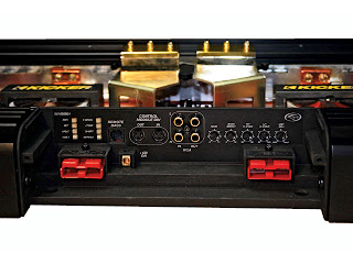
That's the conceptual picture, pretty much devoid of the details. At this point you may be thinking, "That's too easy" or "Why hasn't this been done before?" While the concept is easy, the execution requires a fairly powerful DSP, as well as a fairly powerful brain trust to program the DSP. On this scale (remember this amp puts out 10,000 watts), it also requires the planar transformers with specific coupling and power characteristics.

The DSP is in complete control of the transformers, running a constant pulse of 24kHz. That doesn't mean the transformers are creating a large 24kHz output signal, but that's the clock speed for the pulse-width modulation. When a signal comes into the DSP, it sends off/on pulses to the transformer switchers of the appropriate duration to create both the frequency and the amplitude of the output. In a pulse width modulation format the length of the pulse will correspond to the output voltage level, and in this amp the length of the pulses will be limited to 1/24,000 of a second. A maximum pulse (100 percent) will result in maximum power output, while a half-length pulse (50 percent) results in half power. At idle, there's zero current going through the transformers, but it's still happening at 24kHz.

This is where the amp is like a Class D amp. If the transformer is completely accurate (not possible, by the way) the output will consist of really large squared waves. In reality, the transformer will round these square pulses considerably, plus there's an output filter consisting of a coil and capacitor(s) to finish converting the squared pulses to nice round sine waves. The output filter coils in the Warhorse actually look just like large transformers that would be used in the power supply of a big Class AB amp.

So you now have output signal to feed your speakers, and it should resemble the analog input signal that came into the DSP to start with. The DSP takes feedback from the speaker outputs and makes real-time adjustments to the pulses to create a more accurate reproduction of the original signal, only lots bigger.

There are two separate sets of speaker outputs on the Warhorse, but they're not parallel. You have to use both of them and you have to use them on a dual voice coil speaker, one output to each coil of the speaker. One set handles the positive side of the wave and the other handles the negative side. The + and - labels on the amp correspond to the labels on the speaker's voice coil terminals. At full power this amp is making around 141 volts between 20Hz and 200Hz. Household AC is 120 volts at 60Hz. If you fed the amp with a 60Hz signal, you could probably use it as a backup generator for your house, so don't mess around with the speaker outputs when this amp is on.

Performance
The amp tested as advertised in all respects. The frequency response is exactly 20Hz to 200Hz at the -3dB points, though we used +0/-1dB for the test results. The crossovers and bass boost are exact as well, which is a direct result of the signal being handled in the digital domain by the DSP chip. Power at 14.4-volt input exceeded 10 kilowatts by 350 watts-the equivalent of a decent subwoofer amp. While 10,000 watts is pretty impressive, the fact that the WX10000.1 can deliver it with almost 90 percent efficiency is amazing. Class AB amps hover around 50 percent, so this amp can deliver almost twice the output power for any given power input. You can feed two of these amps for the price of one.

There was no indication on the scope of any turn-on or turn-off noise. Who needs a 10,000-watt turn-on pop?

Slew rate and damping factor have been omitted from this test due to the way the amp works and the importance of such specs for an amp of this size. Testing was complicated by the fact that the DSP is instantly responding to the output feedback. The compensation by the DSP resulted in a negative ratio for the damping factor. The precision of the DSP also resulted in a very low slew rate at the output, which corresponded very closely to the actual slope of a wave at 200Hz. In other words, we were only able to measure what the DSP was causing the amp to do, rather than what it might be capable of.

Manual
The owner's manual is a pretty comprehensive affair. In fact, I suggest you read the manual before purchasing the amp, just to make sure you're equal to the commitment. The manual is where you learn about having to build an electrical substation to feed the beast. Yes, I'm exaggerating but seriously, Kicker recommends no less than eight batteries of 800cca plus two alternators putting out 200 amps each. That's in addition to the battery and alternator just to run the vehicle. As well, you have to run ought-gauge cable everywhere to boot.

Besides the electrical requirements, and the structural mounting bracket, the manual shows several wiring configurations, and explains the controls clearly. The warranty is three months (consumer installed) or two years when installed by an authorized dealer.

Conclusion
Kicker has managed to break new ground here, and do it in a big way. The Warhorse is expensive, but it's intended for use in decibel machines and show systems. The retail dollars-to-watts ratio is a pretty high 97 cents, but using this amp will reduce the overall cost of batteries and alternators due to its high efficiency. Check out the Kicker Warhorse van making appearances around the country if you want to experience what this kind of power is all about.


Test Results
Output power @ 1% THD, 50Hz, 14.4 volts
Mono @ 4 ohms 1 x 5,494 watts
Mono @ 2 ohms 1 x 10,350 watts
Output power @ 1% THD, 50Hz, 12.5 volts
Mono @ 4 ohms 1 x 4,050 watts
Mono @ 2 ohms 1 x 8,052 watts
Distortion at rated power, 50Hz, 14.4 volts 0.66% @ 2 ohms
Input sensitivity 165mV to 5.2 volts
Frequency response (+1dB) 25Hz - 170Hz
S/N ratio (A weighted, below clipping, min. gain) >82dB
Idle current 3.5 amps
Maximum current consumption, unclipped 801 amps @ 10,350 watts
Efficiency at one-third power, lowest impedance 88%
Efficiency at full power, 1%THD, lowest impedance 89.7%
Crossover slope 24dB/octave
Crossover range, lowpass 50Hz - 200Hz
Crossover range, highpass 20Hz - 60Hz
Low-frequency boost +18dB @ 40Hz
Dimensions 35"L x 17.75"W x 3.75"H
Weight 66.8 pounds

Soldering Techniques

Soldering is a simple efficient and reliable way to make electrical connections. The most common reason people are not successful in making good solder connections (joints) is that they do not properly heat the components which are being soldered. Some people apply the solder only to the tip of the iron. This will most likely result in a 'cold' solder joint. Cold solder joints will almost always fail. The only time that you should apply the solder directly to the iron is when the iron isn't conducting the heat to the parts. When the COMPONENTS being soldered are hot enough to easily melt the solder, you know the components are hot enough to make a good quality solder connection. Be sure to keep the soldering iron clean. The oxidized solder which will start to form on the outer surface of the tip of the iron is an insulator and will prevent good heat conduction to the electronic components. If you use a wet sponge to clean the iron, be very careful. If there is a large quantity of solder on the tip and you press hard on the sponge (compressing it a significant amount), as the iron slips off of the sponge hot solder may be thrown off of the sponge (and it still may be very hot). I think it may be better to use something like a coarse steel wool to clean the iron. I also believe that the wet sponge may significantly reduce the life of the tip.

Selecting a Quality Iron

If you want a really good iron, I would suggest that you buy a Weller WP35 iron. I have used them for a very long time and they are very reliable. A WP35 (approx $35) is a 35 watt iron which is suitable for almost everything that you will need to do in car audio or electronic repair work. DO NOT buy a $5 iron and expect it to last very long. The tips of cheap irons are usually just bare copper which quickly oxidizes and cannot properly conduct the heat to the components. The tips on the WP35 are steel clad copper which last for months at a time, even when they are used for more than 8 hours a day. The tips are also available in different sizes. The wider thicker tips are more suitable for soldering larger components.

Soldering Flux

Flux is used to help keep oxygen out of the connection and helps to float contaminants to the surface. It may also help to conduct the heat to the components. Virtually all solder designed for soldering electronics has a core which contains flux. When buying solder for electronics, make sure the flux is not an acid flux. Acid flux is used to solder non electronic components like sheet metal. Flux is also available in a paste form but I rarely use it.

Desoldering

If you have ever tried to remove electronic components from a circuit board (especially multi legged components), you know that it is difficult to remove the old solder without some help. The 2 least expensive, quickest devices to remove the solder are desoldering braid and the desoldering pump. Desoldering braid is simply a flux coated copper braid usually about .1"-.15" wide. To remove the excess solder with braid, you simply apply heat to the braid while the braid is in contact with the solder. The braid will wick the melted solder from the circuit board. The desoldering pump is a device which creates a vacuum to suck up the melted solder. The one I use has a spring loaded plunger which you 'cock' prior to each use. Then when the solder is melted, put the tip of the desoldering pump on the solder joint and release the plunger by pressing (depressing) the release button. For me, it works better if the iron is left on/in the solder while sucking the solder. This will result in a slightly shorter life of the desoldering tip but I have better results. I would recommend buying a 'Soldapult' brand desoldering pump. A large professional quality model is about $30 and will last a very long time. I've used mine professionally for about 5 or 6 years and they are still going strong.

Building with Acrylic


Acrylic Sheeting/Plexiglas:

Acrylic sheeting is widely known as Plexiglas©. Plexiglass©, however, is the name given to acrylic sheeting manufactured by Atofina. The same acrylic type sheeting is also known by the names Acrylite©, Lucite© and Perspex©. From this point on, I'll refer to it simply as acrylic.

Before we go any farther... Do not peel the protective coating from the sheet until the last possible moment. Acrylic sheeting is very easy to scratch. It may be even easier to scratch than CDs.

Cutting Acrylic:
There are a couple of different ways to cut acrylic. Since my experience is mainly with thin acrylic sheeting (1/2" or less), that's what I'll cover.

Table/Circular Saw:
For rough cutting acrylic, you can use a table saw or a circular saw with a fine blade. Blades with fine closely spaced teeth (like those used for plywood) will work relatively well. Blades with widely spaced teeth (like the type used for cutting MDF) will cause a lot more chipping. I've used an Oldham B7254760 on a circular saw with good results. When using a hand held circular saw, use a guide to make sure you get a straight cut with minimal chipping. There are blades made specifically for cutting acrylic. If you're going to be cutting a lot of acrylic or are using very expensive (thick) material, you need to invest in a blade specifically designed for cutting plastics and laminates.


Jig Saw or Band Saw:
Jig saws can be used to cut acrylic when you need something other than a straight cut. To reduce the work of cleaning up the cut, use the finest blade that you can find. Blades with reduced depth (like those used for scroll work - shown below) will work best due to less friction and less resistance when turning the blade. You'll have to experiment with cutting speed to see what works best. Too much pressure can cause excessive chipping. Going too slow may cause the acrylic to melt. If the acrylic melts when cutting, use a light lubricating oil. Have someone apply the oil to the blade as you're making the cut. DON'T use an aerosol dispensed oil. The propellant may be flammable and may be ignited by the jig saw motor. I've had good results with the blade shown below.


Router:
A router can be used to cut acrylic for either straight or curved cuts. For curved cuts, you'll want to use a router with a collar and a guide (pattern or jig made with 1/4 inch plywood). You'll want to rough cut the material within ~1/8 of an inch of the desired finished shape. Trying to cut too much acrylic will lead to melting of the material. Again, you'll have to experiment with the speed of the cut. To prevent chipping, make sure the blade is not allowed to break contact with the cut edge. If it does break contact with the material and you push the router blade back into the edge too quickly, the cutter may chip the acrylic. You also must make sure you have a sharp bit (carbide recommended) to prevent melting of the material. Again, you'll have to experiment to see what works best for you.


Score and Break:
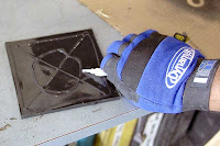
Thin acrylic sheets (less than ~1/4") can be cut much like regular glass. Instead of using a hardened wheel to chip a line in the glass, you'll use a scoring tool to cut a deep scratch in it. The cutting edge of the scoring tool looks something like a single tooth of a table saw blade (but much thinner). You apply pressure to the tool and drag it along a straight edge guide (which should be clamped securely in place to prevent it from moving). You need to continue scoring the acrylic until the cut is ~1/8 of the way through the material (it may take 20 passes on 1/4" thick stock). After that's done, you'll have to clamp it down on the edge of a table (or something similar). The edge of the table needs to align with the cut. The edge of the table needs to be perfectly square (a radiused edge on the table won't provide the proper stress along the desired cut line). It needs to be clamped very securely so that it can not flex or move. You'll then apply pressure to the piece that's beyond the edge of the table until it snaps. If it was cut deeply enough, it will break cleanly along the desired line. If it was not cut deeply enough, the cut (on the side opposite the scoring) can be as far outside of the desired cut line as the thickness of the material. The image below shows an inexpensive scoring tool (I think it cost ~$3)


Polishing the Edge of the Cut:
Depending on the quality of the cut and the desired end use, the edge may need to be polished. When using the acrylic as a window on a speaker enclosure or for an amp rack, you'll probably want to polish the edge. To make things easy, use a rubber or foam block and waterproof sandpaper. Since it will be nearly impossible to keep the edge perfectly square, I'll usually round it off. With a foam sanding block, start with rough paper (~180 grit). Wet sand with lots of water until the edge is uniform and relatively smooth. Then change to finer and finer paper until you get a satin finish with 600 grit paper (180, 360 and 600 grit will work fine). Remember to use lots of water.

Flame Polishing:
After the edge is polished to a satin finish, you may want to get it to a glass like finish. To do this, you can use a propane torch. Let me recommend that you practice on a scrap piece first. Using a propane torch, you very quickly pass the torch over the edge. You must move the torch very quickly. If you go too slowly, the acrylic will melt and boil. This will leave bubbles in the surface. This is from heating the acrylic too deeply. You only want to heat the very outermost edge/surface to its melting point. This will allow it to flow into a smooth glossy surface. As long as you're moving very quickly along the acrylic, you're not likely to cause bubbles (even if you're using the hottest part of the flame).

Practicing Flame Polishing:
The material that a CD is made of reacts similarly to that of the acrylic sheeting. If you want to scuff up a CD with some 600 grit paper (and water), you'll be able to remove most of the finer scratches and haze with the torch. Remember... Move VERY quickly along the surface. Allow the CD to cool between passes with the torch (just as you would when polishing acrylic). Don't you use a good CD. Try it with one that will not play. Heating the CD will cause it to cup slightly and it probably won't play anymore. This exercise is only to allow you too see how the process works. Two final suggestions... Don't burn yourself and don't burn your parent's house down.


Drilling Acrylic


Spiral Bit:
Standard spiral drill bits will not work well on acrylic. Their cutting angle is too aggressive which causes it to try to cut too quickly. This will lead to cracking and chipping around the hole. If you want to use a bit that can be used for metal also, try a bit like the one shown in the following photo. You can see that the main cutting edge is flat instead of angled like a normal bit. This causes the material to be cut in a more controlled fashion. If you don't want to spend the money on a new bit, you can grind a regular bit to the same profile.


Forstner Bit:
Forstner bits are very high quality bits that are generally used for woodworking. They make a very clean hole with little or no chipping. When used for drilling acrylic, you may need to use a cutting lubricant. I generally use a '3 in 1' type oil. Apply the oil to the cutting surface prior to drilling and to the drill bit shaft as you're moving through the material. If the bit is used dry, the friction between the sides of the bit and the material will cause the acrylic to melt (very bad). When used with lubricant, the hole will be very clean.


Standard Woodboring Bit:
Some people recommend against using woodboring bits but I've never had a problem with them. One advantage of the wood bit is the long centering point. This point will exit the other side of the material before the cutting edge. This allows you to turn the material over and drill from the other side. Since the cutting edge will not be pushing out as the bit cuts through surface of the material, there will be little or no chipping on either side of the material.


When using any of the different bits for drilling acrylic, you should:
  • Go slow. Do not force the bit to cut too quickly.
  • Use a drill press. This allows you to have much more control over the cutting speed and assures that you're drilling the hole perfectly perpendicular to the material. You should clamp small pieces down. If the bit grabs the material and spins it, it will cut you. Small pieces don't allow you to get a good enough grip to prevent the piece from spinning with the bit.
  • Practice on a piece of scrap material. If you crack a piece of acrylic after you've already polished the edges, you are not going to be happy.
  • If the acrylic melts as you drill through it (regardless of rate of rotation/feed), try using a light lubricating oil to reduce friction between the bit and the acrylic.

    Fasteners:
    When screwing a piece of acrylic down, you'll need to use some type of washer under the screw. Fiber, plastic and rubber washers will work. If you can't find those types of washers, standard metal flat washers will be better than nothing. If you use washers, you're less likely to crack the material if the screw doesn't go in prefectly straight. Predrilling the hole in the wood will help assure that the screw goes in straight. When tightening the screws, do not overtighten (especially when the surface under the acrylic is not hard). If there's a soft gasket under the acrylic, overtightening the screw will cause the material to crack. You should also use pan head screws (those with a flat mating surface under its head). Using bevel or bugle headed (drywall) screws will cause the acrylic to crack

Kicker ZX350.4 -- Clarity With Agressive Looks

Kicker's impressive ZX350.4 amplifier.

Stillwater Designs, now better known as Kicker, is an "All American" company that's been around a long time. Back in the day, they originated the "kicker" box before anyone else even thought about it - that's probably why people still refer to them as "kicker" boxes. In the early 1990s the company started building amplifiers and has since quietly grown into a large force in the market. This time we take a look at the latest stage in the evolution of the Kicker amplifier, the ZX350.4.

Description
Kicker rates the 4-channel ZX350.4 amplifier at 60 watts per channel into 4 ohms, 90 watts into 2 ohms and 2 x 175 watts bridged into 4 ohms. The amplifier is an unregulated Class A/B design with both RCA and speaker-level inputs, and crossover and bass boost for each pair of channels. Visually, the amplifier retains its family resemblance to Kicker amps from the past several years. It has predominantly a textured black finish with a trio of rubber-capped knobs for each channel on the top plate. Swooping "V" contours in the top sheet metal frame the Kicker badge, and a red strip of silicon rubber lines the top plate on both sides.

The ZX series is an "upside-down" style amplifier. The main chassis is an aluminum extrusion that forms the bottom and sides of the amp. A cover plate made of stamped steel with the design and vents embossed in it covers the top of the amplifier. Adorning this piece are two badges (one for the logo and the other for the model number) and the control knobs for the gain, crossover and bass boost. The cover plate fits into two red silicone-rubber extrusions along each side of the heatsink. The molded plastic endcaps hold it in place.

The power/ground/remote terminal, two 20-amp fuses and the power/protect indicator light are all found on the left endcap, while the speaker connectors, RCA and hi-level inputs, fader and crossover switches are on the right endcap. Crossover frequency, gain controls and bass boost level controls are located toward the right-hand side of the cover plate.

The circuit layout inside is pretty much what you'd expect from looking at the outside. The power supply and the amplification/output section each occupy half of the main board, with an empty 1" strip running right down the middle as a buffer between them. There are other ways of controlling noise from the power supply, but it looks like isolation is important to the engineers at Kicker. The preamp section is nicely contained on a daughter board suspended above the output end of the main board. Both circuit boards are double-sided, but the preamp board uses mostly surface-mount parts while the main board uses all through-hole parts.

Starting with the power supply, power and ground is accepted through two large brass blocks. These two blocks will accept up to 4-gauge cable, although the manual recommends 8-gauge for this one as it is the smallest 4-channel in the series. B+ runs through a pair of 20-amp fuses and a small inductor. It then goes past three 2,200F capacitors for primary filtering and on to two pairs of high-speed, 49-amp switching Mosfets. A TL494 pwm controller drives the switching through the toroidal transformer at about 36kHz, achieving rails of + and - 30VDC. Secondary filtering consists of four 3,300F capacitors to stabilize the rails.

Jumping over to the input section, the first thing I noticed is that the signal grounds are extremely well isolated from the chassis ground. With 40k ohms of isolation, this amplifier will never participate in any ground loops in your system - that's for sure. The signal and shield conductors from the RCA are all fed into low-noise op-amps, thus making this a differential input. This style of input will better reject noise radiated into your RCA cables. The owner's manual reinforces this format by recommending twisted-pair cables rather than big fat coaxial RCAs. Differential inputs are typically found on more expensive amplifiers and have the potential for much better sound quality than less expensive designs. The gain control is accomplished through additional op-amps, rather than the cheaper (and noisier) style of attenuating the signal to ground.

Lastly, the output section consists of four complementary pairs of TIP35C/TIP36C output transistors, each capable of dissipating 125 watts, or 250 watts per output channel, which is more than adequate for this unit.

Performance
The amp performed well on the bench, meeting or exceeding every specification as listed in the owner's manual. The S/N ratio was a very respectable >94dB and the frequency response measured 13Hz to an astonishing 66kHz. The crossovers drifted ever so slightly from the published spec, but the difference was small and the curves were textbook. While filters are spec'd at 50Hz to 200Hz, the lowpass range was measured 54Hz to 203Hz, and the highpass was 45Hz to 180Hz. The bass boost was right on with the published 18dB boost, but centered at 41Hz rather than 40Hz. Trust me, you're not going to hear the difference on any of this.

The protection circuits worked well, both short-circuit and thermal. I like that they're self-resetting so you don't have to turn the system off and back on. On the bench the amp fired up smoothly and there was no turn-on or turn-off noise in the car at all.

Manual
The owner's manual really cuts to the chase. On page 2 there's a place to write down the purchase details; then it tells you how to mount the amp. Wiring is next, still on page 2, and then it slows down a little to cover different system configurations and the setting of controls. Page 5 covers troubleshooting and specifications, while pages 6 and 7 are the warranty covered in four different languages. Speaking of warranty, Kicker provides a 2-year deal when purchased from an authorized dealer. As always, keep your receipt.

Listening
The ZX350.4 was installed in the trunk of my Buick and initially connected to the front separates and the rear 6 x 9s. The crossovers were set for fullrange and the subwoofer was not hooked up.

I started out as always with Donald Fagen's Kamakiriad, which is a very well-mastered recording. There is a lot going on in all of these tracks, so it can really reveal any shortcomings with the amps and speakers. Track 1, "Trans-Island Skyway" starts out with a guitar riff, adding bass, keys and percussion as the intro builds. The bass line is pretty busy and can sound muddy, but the Kicker came through. Not only was the bass clean and clear, but everything else sounded distinct and well-balanced. The center image was a little fuzzy and quite low. I checked out "Tomorrow's Girls" for the highs. The cymbals in the intro were clear and smooth. "Snowbound" revealed good low-end clarity on the Fender Rhodes keyboard and bass guitar.

Tracks from Dada's Puzzle and Mary Chapin Carpenter's Come On, Come On reinforced my initial impressions that the response and clarity were excellent, but the image remained low and somewhat indistinct.

I returned to the trunk and changed the configuration. I kept the front separates connected but set the highpass to 100Hz. The other 2-channels were bridged and connected to the subwoofer with the lowpass set to the 100Hz. I repeated some earlier tracks with good results, and then went to "Posters" on the Dada CD. This one starts out with a great drum solo, adding electric guitar along the way. It sounded great, but didn't get as loud as I really like it. No foul here, it's just a smaller amplifier than I have permanently installed. In this configuration it should put out 60 watts each to the front speakers, and 175 watts to the subwoofer, where I normally have 100 watts to each corner and over 300 on the subwoofer.

Conclusion
I like this amplifier a lot because it did what it said it would do. The Kicker ZX350.4 is a very straightforward unit that is usable in several configurations. When auditioning the amp in my car I didn't feel the imaging and staging were as good as my reference amps, but I realize that it's not an issue for most people. However, clarity and frequency response were very impressive and that's something every consumer should be concerned with.

The ZX350.4 is stylish, somewhat aggressively so. At a retail price of $349, and a max power of 387 watts, it comes in at 90 cents per watt. As a general rule, anything with a retail price under a dollar per watt is not bad (for an amp below 500 watts). Overall it's a good amp at a reasonable price.


Hidden Lightweight Performance - Fiberglass enclosure construction

Fiberglass enclosures have many benefits. Their ability to conform to unusual shapes allows you to maximize the enclosure volume in tight spaces. However there are trade-offs. Compared to MDF enclosures, fiberglass enclosures have a tendency to resonate. Also fiberglass construction requires significant preparation before you actually begin. It would be great if you could combine the benefits of a solid, easy-to-build MDF enclosure with the benefits of light-weight and unusual shapes of fiberglass enclosure. Now you can with the Dynamat fiberglass enclosure method.

The goal of this project was to build an enclosure that was completely hidden behind the factory side panel. Here is the step by step process.

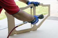
Step 1: Build a frame work for the enclosure. The bottom and front panels of the enclosure are built using MDF. Save the cutouts of the front frame work for later in the build.


Step 2: Once the frame work is sized up, remove and use the front frame to trace the front baffle. Make sure to trace the inside as well as the outside


Step 3: Assemble the frame work. Notice that the cut out brace allows air flow while increasing the stiffness in the center of the enclosure.


Step 4: TacMat, placed behind the frame work, is used as the enclosure back wall. TacMat cushions and insulates the fiberglass from the vehicle, forming a non-resonant composite enclosure. This stops the squeaking noises common with fiberglass/metal contact. Once the TacMat is positioned, use a marker to trace the edges of the frame work.


Step 5: Working outside the vehicle, hot glue the TacMat to the frame. Trim to fit. Once completed, reinstall in the vehicle.


Step 6: Tape off and protect the area to fiberglass. TacMat does not require taping off the area behind. This is a great time saver. Notice how the TacMat is pulled above the frame. This will be trimmed off after the fiberglass is set.


Step 7: Fiberglass the enclosure. Make sure to pay special attention to sealing the front framework to the fiberglass and TacMat. The quality of the bond will determine the quality of the enclosure. For best results, use multiple small strips of fiberglass cloth. Build up the enclosure so that the fiberglass is approximately ¼” thick. Trim off the excess TacMat around the vehicle.


Step 8: Once the fiberglass is completely cured, remove the enclosure from the vehicle. For best results, wait 24 hours to remove the enclosure. This will ensure that the shape remains intact.


Step 9: Next apply DynaSpray (Dynamat’s liquid damping material) to the inside of the enclosure. This will further damp the fiberglass enclosure. The combination of TacMat and DynaSpray transforms the fiberglass into a non-resonant enclosure.


Step 10: Notches were placed in the front of the enclosure to clear mounting tabs for the factory panel. These holes are sealed with Kitty Hair (fiberglass strands suspended in body filler). Follow instructions on the product for best results.


Step 11: Taking the cut-outs from the front framework, adhere Dynamat Original by applying adhesive to the logo side of the product and the panels. For best results, use and upholstery grade adhesive. If you do not have access to that, you can substitute 3M Super 77.


Step 12: Remove the Dynamat Original release liner and apply to the front baffle. Use the guides you traced in Step 2 for alignment. The benefit of the double thick baffle with Dynamat Original is two fold. The thicker baffle provides an extra sturdy mounting for the woofer. By sandwiching Dynamat Original between the two MDF panels, the result is an internally damped front baffle that is extremely dead. Rapping on it with your knuckles sounds like concrete!


Here’s the look of the enclosure he so far.

Step 13: Tile DynaXorbs on the back wall of the enclosure. DynaXorbs are designed to absorb the back-wave noise and distortion of the subwoofer. The results are reduced internal enclosure reflections which enhance the sound quality of the subwoofer.


Step 14: Apply masking tape to the backside of the woofer mounting hole. This is a simply way to ensure that adhesive sprayed to the exterior of the enclosure does not get inside the enclosure. When mounting the front baffle to the enclosure, nails work fine but screws are preferred. Screws ensure a tight bond between the front baffle and enclosure.


Step 15: Cover the enclosure. Use your desired finish for your enclosure. I chose a simple trunk liner because my enclosure is hidden behind the factory side panel.

Using this construction method, I was able to construct a 1 cubic foot enclosure that hides behind the factory side panel. Resonances typical in fiberglass construction are non-existent. The enclosure is roughly half the weight as a comparable MDF enclosure. Not to mention that a enclosure this size would not have fit behind the factory panel.


This woofer is definitely heard but not seen. The JL Audio 8W7 (yes an 8 inch) is able to achieve a respectable 129dB when tuned for sound quality. With great low-frequency extension, the sound is effortless and the performance is much larger that the 8 inch woofer


top